Tuesday, April 28, 2015

Week 4: Timer Switch Use (Pros versus Cons)

One issue our group is facing is how the wiring is going to be setup. We need to figure out how to run the timer using a breadboard. Some problems we may face are actually getting the timer to run and programming it run at certain periods of times. The timer runs on 120v AC and 5 Amps, we need to figure out how this is going to be put into a circuit because  it uses a lot of power which is very dangerous.

Fig 1. Timer Switch (Closed)

Fig 2. Timer Switch (Open)

Thursday, April 23, 2015

Week 4: The Frame (Pet Feeder Container)

Parts are finally starting to arrive in the mail! We have ordered several parts (some which have since decided against using) and expect to start assembly once they are all here.

The frame --which all pieces, parts, and covers will be assembled around arrived --earlier this week. It is essentially a cake tin that is 3 inches deep and 12 inches diameter. It is a lot larger than I imagined it would be. This is okay because I (speaking for myself only) was afraid that it would be too shallow.

[PIC]
But all is well :)

The tin encompasses 332.29 square inches of space. This is approximately tantamount to 23 cups.

Coming soon, there will be more information on the inner compartments which will divvy up these 23 cups. Ideas of how this intersections will be placed can be made when the rest of the mechanical pieces arrive in the mail.

The image in the post below (Fig.1) is an idea of what the compartment might look like, but it will change. For one, it will have to have a hole in the middle. Second, the slope closest to the center axis will likely change to accommodate a specific configuration of mechanical pieces, which have yet to be designed.

More on this next week.

Tuesday, April 21, 2015

Week 4: Segmented Food Tray

Now that the cake pan (feeder container) has arrived, the next step is to design the inner compartments that will be used to separate set food amounts. The most ideal method would include the use of the Creo Parametric 2.0 CAD program to design one tray that has 8 distinct compartments for pet food (See Fig 1.).

Each compartment would be of equal size and volume and walls between compartments would be sufficiently thick enough to prevent pet from accessing the next compartment's food supply.

Use of a CAD program and the 3-D printer ensures that the tray (that has specifically been designed for this model) will fit into the cake pan perfectly, leaving no room for food to escape or move around once pet feeder has been activated.

Fig 1. CAD Tray Design in 3-D

Specific details that relate to measurements needed for the CAD design process can be found on the Tutorial page

Monday, April 20, 2015

Week 3: Timer Switch (Timing Intervals of Cover Rotation)

We are going to use a timer switch instead of an Arduino. We found this to be more effective in the way our cat feeder is going to work. A timer switch is a timer that operates an electric switch controlled by the timing mechanism. The switch is connected to a circuit operating from a circuit connected to a breadboard. We will wire the switch so that the motor that will be connected to it will be given power for only certain amounts of time and throughout the day for as many days as the user would like.


Week 3: Arduino Use (Possible Switch to Digital)

An Arduino is a microcontroller that can run on a DC battery or a USB port in a computer. This system allows the user to input certain commands using the Arduino programming language. The commands allow several real life applications. The Arduino can do things like create a light show that controls several LEDs, or gauge water flow. However, initially, this group intended to use the Arduino to control the movement of a motor that would rotate the top of the pet feeder.

This is an Arduino Uno, which is an example of an Arduino the group was going to use
In the past lab session, the group was trying to figure out a ways to incorporate the Arudino in the project properly. The initial issue with the Arduino was trying to learn the language for the Arduino, which was very different from any of the programming that the group has done in the past. However, the group still tried to learn the coding by looking at certain samples. After trying to insert code that the group created and not having it work properly, some of the members found examples that would run a simple DC motor, but they did not work properly either. Even though the group did not receive any results, it still continued to research more on how to make the Arduino work. At the next meeting the group decided that using an Arduino in this situation would not be practical because if a person were to purchase this pet feeder, he or she would need to have a computer, and knowledge about programming. In addition, the group determined that there may be some unpredictability with the Arduino is something went wrong with the code. Finally, the group decided that a timer switch would be best for this project, which the group will write more about in the future.

Week 3: Gear Research & Calculations (Mechanical Approach)

Since we are now sure that gears will be an integral part of the project, it is time to decide how exactly.

The RPM of the motor which connects to the power system via potentiometer will have to be reduced using gear ratios. With 8 compartments and the maximum number of feedings per day being 4 (see first post) the pet feeder needs to rotate 45 degrees (360degrees/8compartments) every 6 hours (24hrs/4feedings).

So a hypothetical motor that rotates with a speed of 400RPM would need a lot of reducing. While it seems lofty, this is possible with 4 sprockets.

[PIC]

The first unit is the motor itself rotating at 400RPM
The second unit (1) rotates at 1RPM*
The third (2) rotates at 1 rotation per hour
The fourth (3) rotates at one rotation for every 6 hours in units of ___ degrees
The fifth unit (4) rotates at one rotation every 48 hours in units of 45 degrees

*The connection between unit one and unit 2 may be expanded.

Research on the Geneva gear:
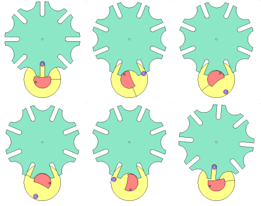
The final unit can operate in a number of ways. It needs to rotate with 1/8th of it's teeth in short bursts every 6 hours. The Geneva gear is a mechanism that can help our system execute this kind of motion.
Here is an example of this dynamic connection type:


<---Unit 4 rotating 45 degrees every 6 hours


<---Unit 3 rotating 360 degrees every 6 hours


In simulation of this connection type, a dilemma was presented. For unit 3 to rotate the (approximately) 120 degrees needed to move unit 4 for one 45 degree step, 2 hours would need to pass. In other words, it would take 2 hours of motion for one compartment to open.

This is a problem. Other avenues will have to be explored.

Friday, April 17, 2015

Week 2: User Notification (Use of an LED)

One issue that the group was thinking about was how to notify the owner once the pet feeder has rotated a certain amount. The group reached the consensus that the best method of making the owner aware that the container is empty is by placing an LED light at the side of the pet feeder.


Initially, the group was considering to implement an alarm that would send out a low noise when the feeder would have rotated a full rotation. However, the group figured that an alarm would scare a cat off so the group decided to use an LED. The group believes that this would work when the top of the feeder fully rotates, it will set off a switch,which will in turn turn on the LED notifying the owner to replace the food. Then the owner will rotate the top of the feeder back around and turn the feeder back on. This seems to be the most effective, inexpensive and pet-friendly method of making the owner aware of the empty pet feeder.